Common problem
Capacitance function and classification
As one of the passive components, the capacitor is used in the power circuit to realize the functions of bypass, decoupling, filtering and energy storage. The following categories are detailed:

1) Bypass
??Bypass capacitor is an energy storage device that provides energy for local devices. It can uniformize the output of the regulator and reduce the load demand. Just like a small rechargeable battery, the bypass capacitor can be charged and discharged to the device. In order to minimize the impedance, the bypass capacitor should be as close as possible to the power supply pin and ground pin of the load device. This can well prevent the ground potential rise and noise caused by the input value being too large. The ground bounce is the voltage drop at the ground connection when a large current glitch passes through it.
??2) Go to lotus
??Quoo, also known as JieLo. From the circuit point of view, it can always be divided into the source of the drive and the load being driven. If the load capacitance is relatively large, the drive circuit must charge and discharge the capacitance to complete the signal jump. When the rising edge is relatively steep, the current is relatively large, so that the drive current will absorb a large power supply current. The inductance and resistance (especially the inductance on the chip pins will bounce). Compared with the normal situation, this current is actually a kind of noise, which will affect the normal operation of the previous stage. This is the so-called "coupling" .
??The depot capacitor acts as a "battery" to meet the change of the drive circuit current and avoid mutual coupling interference. Combining bypass capacitors and decoupling capacitors will make it easier to understand.
??The bypass capacitor is actually decoupled, but the bypass capacitor generally refers to high-frequency bypass, which is to improve a low-impedance leakage prevention method for high-frequency switching noise. High-frequency bypass capacitors are generally relatively small, and generally take 0.1 according to the resonant frequency? F, 0.01? F, etc.; and the capacity of the decoupling capacitor is generally larger, maybe 10? F or greater is determined according to the distribution parameters in the circuit and the magnitude of the change in the drive current.
??Bypass is to take the interference in the input signal as the filtering object, and decoupling is to take the interference of the output signal as the filtering object to prevent the interference signal from returning to the power supply. This should be their essential difference.
??3) Filtering
??Theoretically (that is, assuming that the capacitor is a pure capacitor), the larger the capacitance, the smaller the impedance, and the higher the passing frequency. But actually more than 1? Most of the capacitors of F are electrolytic capacitors, which have a large inductance component, so the impedance will increase when the frequency is high. Sometimes you will see a large electrolytic capacitor with a small capacitor connected in parallel. At this time, the large capacitor is connected to the low frequency and the small capacitor is connected to the high frequency. The function of the capacitor is to pass high impedance and low impedance, and pass high frequency to block low frequency. The larger the capacitance, the easier it is to pass low frequencies, and the larger the capacitance, the easier it is to pass high frequencies. Specifically used in filtering, a large capacitor (1000?F) filters low frequencies, and a small capacitor (20pF) filters high frequencies.
??Some netizens have vividly compared the filter capacitor to a "pond". Since the voltage at both ends of the capacitor does not change suddenly, it can be seen that the higher the signal frequency, the greater the attenuation. It can be said that the capacitor is like a pond and will not change the amount of water due to the addition or evaporation of a few drops of water. It converts changes in voltage into changes in current. The higher the frequency, the greater the peak current, thus buffering the voltage. Filtering is the process of charging and discharging.
??4) Energy storage
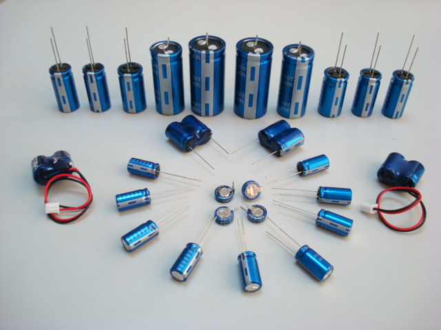
??The energy storage capacitor collects the charge through the rectifier, and transfers the stored energy to the output terminal of the power supply through the lead of the converter. The voltage rating is 40~450VDC, and the capacitance value is 220~150 000? Aluminum electrolytic capacitors between F are more commonly used. Depending on different power supply requirements, devices sometimes adopt series, parallel or combination forms. For power supplies with a power level of more than 10KW, larger tank-shaped screw terminal capacitors are usually used.
??Apply to signal circuit, mainly complete the functions of coupling, oscillation/synchronization and time constant:
??1) Coupling
For example, the emitter of the transistor amplifier has a self-biased resistor, which at the same time causes the signal to generate a voltage drop and feedback to the input to form the input and output signal coupling. This resistor is the element that generates the coupling. If the resistor is two A capacitor is connected in parallel at the end. Because a capacitor of appropriate capacity has a small impedance to the AC signal, which reduces the coupling effect produced by the resistance, this capacitor is called a decoupling capacitor.
??2) Oscillation/Synchronization
??The load capacitance including RC, LC oscillator and crystal all belong to this category.
??3) Time constant
??This is the common integral circuit formed by the series connection of R and C. When the input signal voltage is applied to the input terminal, the voltage on the capacitor (C) gradually rises. The charging current decreases as the voltage rises. The characteristics of current through resistance (R) and capacitance (C) are described by the following formula: ?i = (V / R) e- (t / CR)


